This line is used to draw all the edges of the object. Construction lines and guide lines are very light easily erased lines used to block in the main layout.

Standard Engineering Drawing Line Types Line Art Lesson Types Of Lines Different Types Of Lines
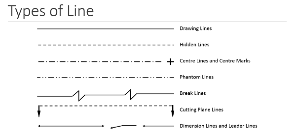
LEADER LINE Medium line with arrowhead to show notes or label for size or special information about a feature.

. Types of Lines in Technical Drawing Object Line. A PFD normally comprise of but not limited to i all the process lines utilities and operating conditions essential for material balance and heat and material balance ii utility flow lines and their types which are used continuously within the battery limits iii equipment diagrams to be arranged according to process flow designation and equipment number iv. Learn vocabulary terms and more with flashcards games and other study tools.
The ISO type K lines are thin discontinuous and chain dotted with a double dot as shown in Figure 314. There are then different types of lines among the main ones are. Technical drawings are used widely throughout many industries by professionals including architects engineers CAD Technicians product designers and mathematicians.
The Line type definition numbers are my own. Each line type has clear meanings on the drawing and mixing up one type with another type is the equivalent of spelling something incorrectly in. E type Dashes THICK.
BS 88882008 Technical product specification. BS EN ISO 128-202001 Technical drawings. Guide line It is used to indicate a.
Measure lines Backside section lines Implied axis lines to state the code of the planes at diagonal lines which are used to state plane surface Intersection Leader Hatching. C type Continuous THIN Freehand. Object lines are solid heavy lines 7 mm to 9 mm.
Within the branch of the technical drawing appears the line a fundamental characteristic of it important to illustrate the different objects. Drawings for interior designprojects generally use three line widths. B type Continuous THIN.
Thick lines are generally twice as wide as thin lines usually V32 inch or about 08 mm wide. It is used to. Below is a list of the various types of technical drawing and their uses.
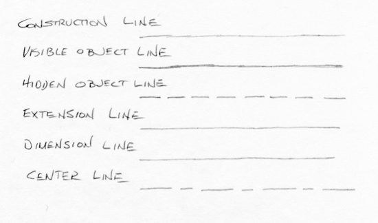
Fold Lines are lines used to represent an object flattened out into a 2D shape the bend lines are represented by long line and two short dashed line and then a long line again as shown on the left. They are drawn as solid lines with a thickheavy weight. Following are the different types of lines used in engineering drawing.
F type Dashes THIN. See answer 1 Best Answer. H type Chain THIN and THICK.
You can define your own but the British standards require that you add a key to your drawing to describe your custom line types meaning. Start studying 12 Types of lines used in technical Drawing. Thick lines for dimension.
A center line is a 3 mm to 5 mm line that alternates between short and long dashes. BS EN ISO 128-202001 Technical drawings. Once again you are free to make up your own line definitions but it is recommended that you put a note on the drawing with their meaning.
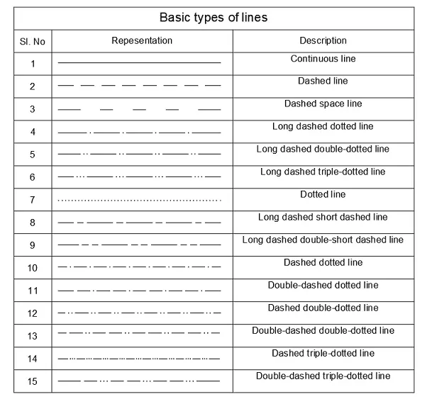
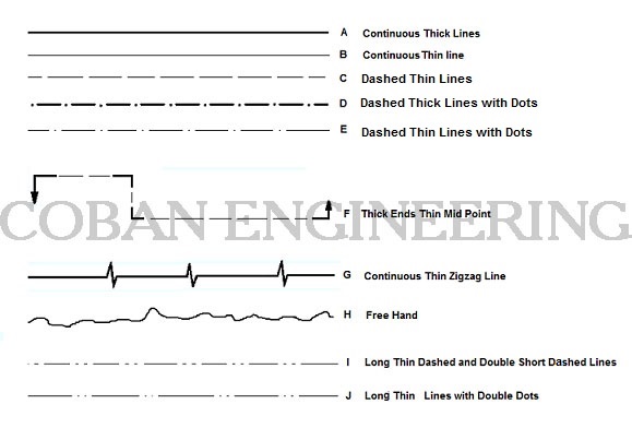
A type Continuos Thick. In this followup to my first line types video I talk about a few more types of lines used in technical drawings. The line types are thick thin continuous straight curved zigzag discontinuous dotted and discontinuous chain dotted.
They are used to indicate the important features of other parts. ORDER OF PRIORITY OF COINCIDING LINES When two or more lines of different types coincide the following order of priority should be observed. Line weight is the thickness of the line.
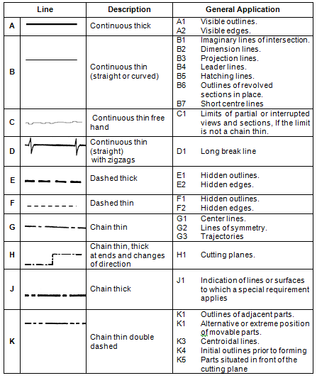
Some of these professions can be broken down into various professions that all engage in technical drawing. Visible lines are the edges or outlines of an object. I Visible outlines and edges Continuous thick lines type A ii Hidden outlines and edges Dashed line type E or F iii Cutting planes Chain thin thick at ends and changes of cutting planes type H iv Centre.
General principles of presentation. General principles of presentation. You should make the line so that end.
A type Continuos Thick B type Continuous THIN C type Continuous THIN Freehand D type Continuous THIN Zig-Zag E type Dashes THICK F type Dashes THIN G type Chain Thin H type Chain THIN and THICK J type Chain. PHANTOM LINE Long line followed by two short dashes use to show alternate position of a moving part. What are the six types of lines in technical drawing.
This video will help you to understand the difference between different types of lines used in technical drawing. You are not limited to these line types. Following are the different types of lines used in engineering drawing.
G type Chain Thin. Centre Line or centreline Extension Line. Examples of this type of line can be seen in the movable jaw detailed drawing.
All other lines contrast with the visible lines by having either a thinner weight andor a combination of dashes. What are the 3 major line types that are used for technical drawings. Line types are also a language type to communicate between technical people.
Surroundings and sides of the matters Outlines of the Edges End of the Screws B. ISO 128 engineering drawing line type J reason eg. D type Continuous THIN Zig-Zag.
This line is used mainly in sketching which is a freehand drawing technique. These lines define the shape of the object portrayed. A measuring area or a limit of heat-treatment.
Using the Alphabet of Lines. Thick dark medium and thin light. Thin lines for outlining.
A hidden line. BS 88882008 Technical product specification. SECTION LINE Medium lines drawn at 45 degrees use to show interior view of solid areas of cutting plane line.
Figure 3-7 These are common line types used in drawings to describe objects hidden conditions and important relationships between components and space.
Engineering Drawing Wikipedia

10 Different Types Of Lines Used In Engineering Drawing

Technical Drawing Standards Line Types
Activity 2a
How To Read Engineering Drawings A Simple Guide Make Uk
Types Of Line In Engineering No 1 Detailed Guide To Line Types
Type Of Lines In Technical Drawings
Technical Drawings Lines Geometric Dimensioning And Tolerancing Definition Of The Drawings Lines Iso Ansi Projected Two View Drawing
0 comments
Post a Comment